Calibrating Semi-Cylindrical Illuminance Meters on an Optical Bench
Summary: Semi-cylindrical meters often claim ±4% MPE, yet a dedicated national calibration regulation is still limited. Optical-bench calibration with luminous-intensity standard lamps is the common practice. This article explains the Esc model, the internal effective reference plane (~0.067×d), stray-light control, and why expanded uncertainty can stay within about 1–1.3% (k=2) for typical points.

Reference plane
Unlike flat-head lux meters, the effective reference plane lies inside the cylindrical receptor, parallel to the entrance window, about 0.067× diameter from the side. Distance on the bench must use that plane—not the outer window face.
Model
Esc = (2 / π) · I / l² with the probe axis perpendicular to the incident ray.
Uncertainty drivers
Repeatability, standard-lamp intensity and current, distance / reference-plane location, and stray light (often larger for cylindrical heads). With primary/secondary lamps, expanded uncertainty at 10–100 lx points can be ~1.0–1.3% (k=2), typically <1/3 of ±4% MPE.
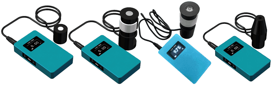
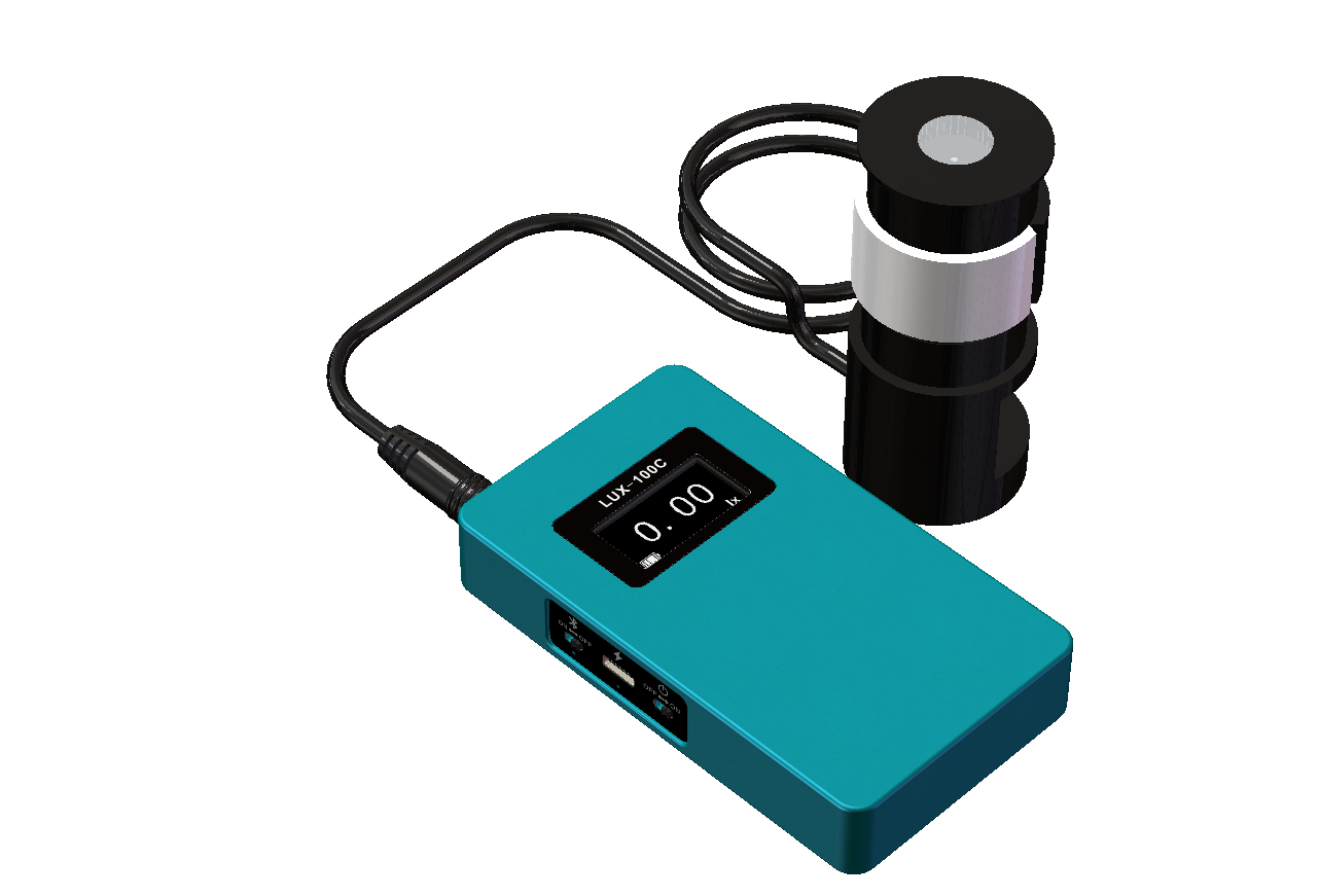
Product reference: LUX-100D-C. Field use: field guide.
FAQ
Q: What is the optical-bench Esc formula?
A: With the probe axis perpendicular to the incident ray, Esc=(2/π)·I/l² (I in cd, l to the effective reference plane in m). This factor is for semi-cylindrical geometry—do not reuse it for full cylindrical meters.
Q: Where is the effective reference plane?
A: Inside the cylindrical receptor, parallel to the entrance window, about 0.067×diameter from the side—not the outer window face.
Q: Why is stray light critical for cylindrical heads?
A: Cylindrical receptors more easily collect side reflections; use baffles/apertures and evaluate stray-light contribution when needed. Ask the lab to state the reference-plane definition and stray-light treatment on the certificate.